
Analyzing the Anti-Sway System Structure in Rubber Tyred Gantry Cranes
- blog@ellsenbridgecrane.com
- Jun 11
- 5 min read

In modern material handling environments such as logistics yards, precast concrete storage areas, steel fabrication workshops, and heavy equipment assembly sites, rubber tyred gantry cranes are expected to deliver not only lifting capacity but also high-precision load positioning. One of the most critical technologies enabling this performance is the anti-sway system.
Load sway is a natural physical phenomenon that occurs whenever a suspended load is accelerated, decelerated, or affected by external forces such as wind or uneven motion. In large-scale gantry crane operations, even small oscillations can lead to positioning errors, reduced efficiency, or safety risks. The anti-sway system is therefore an essential engineering solution that stabilizes load motion and ensures controlled handling.
This article provides a deep technical analysis of the anti-sway system structure in rubber tyred gantry cranes, including its mechanical basis, control logic, sensor integration, and operational significance.

1. Understanding Load Sway in Gantry Crane Systems
Before analyzing the anti-sway system, it is important to understand why sway occurs.
When a load is suspended by wire ropes from a trolley, it behaves like a pendulum. Any horizontal acceleration or braking causes inertia to act on the load, resulting in oscillation. In rubber tired gantry cranes, sway is influenced by:
Trolley acceleration and deceleration
Gantry travel motion
Hoisting speed changes
Wind forces in outdoor environments
Uneven ground or structural vibration
The longer the suspension height and the heavier the load, the more pronounced the swing effect becomes.
Without control, sway can lead to:
Misalignment during placement
Structural impact between load and surrounding equipment
Increased cycle time due to manual correction
Higher operator fatigue and risk
2. Core Objective of Anti-Sway Systems
The anti-sway system is designed to minimize pendulum motion during crane operation. Its goals include:
Reducing swing amplitude during acceleration and braking
Shortening stabilization time after movement stops
Improving load positioning accuracy
Enhancing overall operational safety
Increasing automation capability in semi or fully automated systems
In modern industrial environments, anti-sway control is no longer optional—it is a key performance requirement.
3. Mechanical Basis of Anti-Sway Control
Although anti-sway systems are often associated with software control, the mechanical structure plays a foundational role.
3.1 Hoisting Rope Geometry
The wire rope system determines the natural pendulum characteristics of the load. Key design factors include:
Rope length (suspension height)
Number of rope falls
Drum alignment and winding consistency
Trolley center positioning
A well-aligned rope system reduces uneven tension, which helps minimize induced sway.
3.2 Trolley and Gantry Rigidity
Structural stiffness directly influences vibration transmission. In rubber tyred gantry cranes:
High rigidity reduces structural deflection
Stable trolley rail alignment ensures smooth motion
Reinforced gantry frames minimize torsional effects
Any structural flexibility can amplify sway under dynamic loads.
3.3 Drive System Smoothness
Mechanical smoothness in motion systems is crucial. This includes:
Gearbox backlash control
Motor torque consistency
Tire-ground interaction stability
Acceleration ramp design
Abrupt mechanical transitions are one of the primary triggers of load swing.

4. Sensor Systems in Anti-Sway Architecture
Modern anti-sway systems rely heavily on real-time sensing. These sensors form the feedback layer of the control loop.
4.1 Position Sensors
Encoders and linear position sensors track:
Trolley position along the girder
Gantry movement speed and direction
Hoisting height changes
This allows the system to calculate load trajectory.
4.2 Inertial Measurement Units (IMU)
IMUs detect:
Angular movement of the load
Acceleration forces acting on the system
Oscillation frequency and amplitude
This data is essential for real-time sway prediction.
4.3 Load Monitoring Sensors
Load cells integrated into the hoisting system measure:
Actual lifted weight
Dynamic load fluctuations
Uneven force distribution
These readings help prevent instability caused by asymmetric loading.
5. Control System Structure of Anti-Sway Technology
The anti-sway system is fundamentally a closed-loop control system combining sensor input and motor output correction.
5.1 Open-Loop vs Closed-Loop Control
Early systems relied on open-loop control, where operators manually adjusted movement speed. Modern systems use closed-loop feedback control, where:
Sensors detect load motion
Control algorithms calculate corrective actions
Drive systems adjust motion in real time
5.2 Mathematical Modeling of Sway
The load is treated as a dynamic pendulum system. Control algorithms estimate:
Swing angle
Angular velocity
Damping coefficient
Based on these parameters, the system predicts future motion and applies preemptive corrections.
5.3 Motion Coordination Logic
Anti-sway control is not isolated to a single axis. It coordinates:
Trolley acceleration control
Gantry movement synchronization
Hoisting speed adjustment
The key principle is synchronized motion control rather than reactive correction.
6. Anti-Sway Implementation in Rubber Tyred Gantry Cranes
In rubber tyred gantry cranes, anti-sway systems must adapt to outdoor and variable working conditions.
6.1 Influence of Ground Conditions
Unlike rail mounted crane systems, rubber-tyred cranes operate on concrete surfaces that may have:
Minor unevenness
Surface friction variation
Local deformation under heavy load
These factors introduce additional vibration sources that must be compensated.
6.2 Wind Compensation
Outdoor operation exposes the load to wind forces. Advanced systems incorporate:
Wind speed sensors
Dynamic wind force estimation models
Speed limitation logic under high wind conditions
6.3 Multi-Axis Coordination
Anti-sway control must coordinate three independent movements:
Longitudinal gantry travel
Lateral trolley movement
Vertical hoisting
Any mismatch between these axes can introduce secondary oscillation, making synchronization essential.
7. Advanced Anti-Sway Technologies
Modern systems are evolving from basic damping control to intelligent predictive control.
7.1 Vector Control Algorithms
Vector-based control adjusts motor torque dynamically to counteract swing direction, reducing oscillation faster than conventional PID control.
7.2 Model Predictive Control (MPC)
MPC systems simulate future load behavior and apply preemptive corrections instead of reacting after sway occurs.
7.3 AI-Based Optimization
In advanced terminals, machine learning algorithms analyze historical crane motion data to:
Optimize acceleration curves
Reduce operator-induced errors
Improve cycle efficiency over time
7.4 Automatic Positioning Integration
Anti-sway systems are increasingly integrated with automatic positioning systems, enabling semi-automated or fully automated load placement.
8. Operational Benefits of Anti-Sway Systems
The implementation of anti-sway technology significantly improves crane performance:
8.1 Increased Safety
Reduced swing minimizes:
Collision risk
Structural impact
Load instability during movement
8.2 Higher Productivity
Faster stabilization means:
Shorter cycle times
Reduced manual correction
Improved workflow continuity
8.3 Improved Precision
Load placement accuracy is significantly enhanced, especially in:
Tight storage layouts
Assembly line operations
High-density industrial yards
9. Maintenance and Calibration Considerations
Anti-sway systems require regular maintenance to maintain accuracy.
Key focus areas include:
Sensor calibration accuracy
Encoder signal stability
Motor drive responsiveness
Wire rope tension consistency
Control software updates
Even small deviations in sensor accuracy can affect system performance.
10. Industrial Application Context
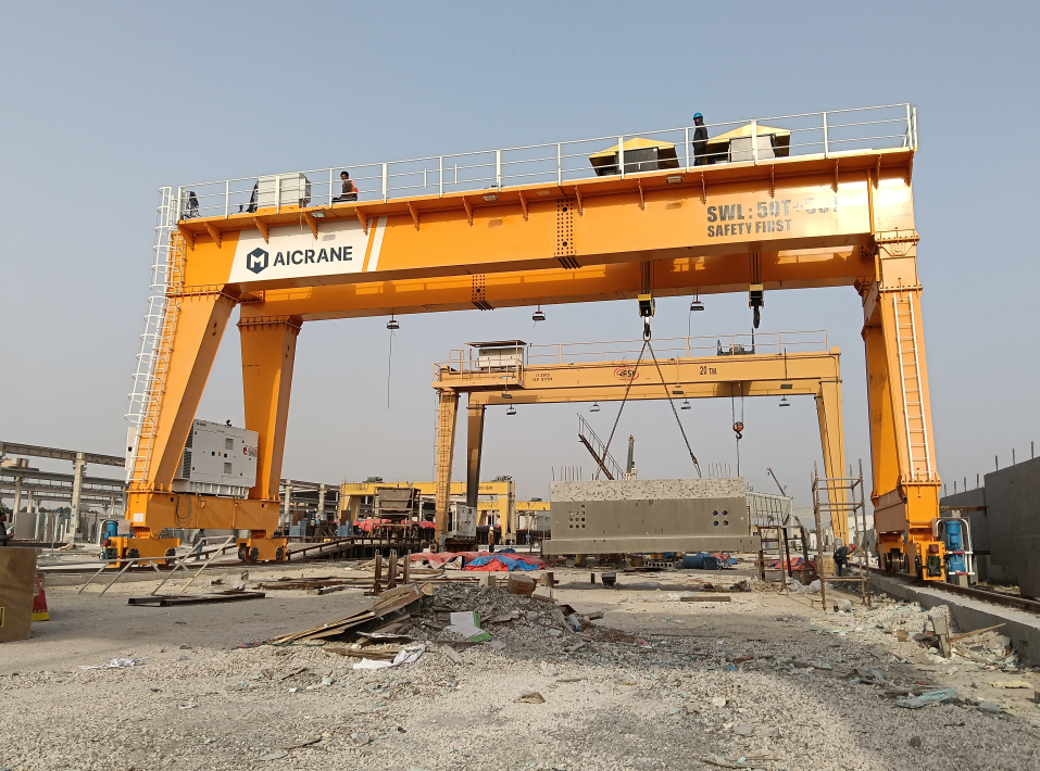
Anti-sway technology is widely used across industries where rubber tyred gantry cranes operate, including:
Precast concrete production yards
Steel fabrication and assembly plants
Heavy machinery manufacturing
Modular construction logistics
Port and inland container operations
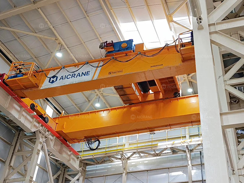
Manufacturers such as Aicrane integrate anti-sway systems into their crane designs to improve operational stability, safety, and automation capability across these diverse industrial environments.
Conclusion
The anti-sway system in rubber tyred gantry cranes is a highly integrated combination of mechanical design, sensor technology, and advanced control algorithms. It transforms a naturally unstable pendulum system into a controlled, predictable lifting process.
By coordinating motion across multiple axes and continuously adjusting in real time, anti-sway technology ensures that heavy loads can be handled with precision, safety, and efficiency—even in complex outdoor working environments.
As automation continues to advance, anti-sway systems will play an even more central role, forming the foundation for fully intelligent crane operations in modern industrial logistics.

Comments